
Page 234 - IS-Rayfast Catalogue - Issue 9, 2017
P. 234
Terminals and Splices
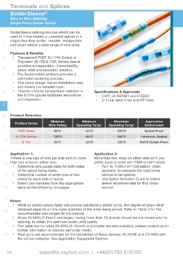
SolderSleeve ®
Wire to Wire Splicing
Single Piece Solder Splice
1 SolderSleeve splicing devices which can be
used to make sealed or unsealed splices in a
single step they solder, insulate, encapsulate
2 and strain relieve a wide range of wire sizes.
Features & Benefits
3 • Transparent PVDF (D-1744 Series) or
Polyolefin (B-155 & CWT Series) sleeve
provides encapsulation, inspectability,
4
strain relief and insulation solution.
• Pre-fluxed solder preform provides a
controlled soldering process.
5
• One piece design makes installation easy
and lowers the installed cost.
6 • Thermo-chromic temperature indicator in Specifications & Approvals
the D1744 splices facilitates termination • CWT: UL E87681 and D-5023
and inspection. • D-1744: NAS-1744 and RT-1404
7
8 Product Selection
Minimum Minimum Maximum Application
Product Series
Wire Rating Operating Temp’ Operating Temp’ Environment
9
CWT Series 85ºC -55ºC 125ºC Splash-Proof
D-1744 Series 125ºC -55ºC 150ºC Immersion Sealed
10
B-155 85ºC -55ºC 125ºC RoHS Splash-Proof
11
Application 1: Application 2:
If there is one size of wire per side and no more More than two wires on either side (or if you
2
12 than two wires on either side: prefer sizes to work with CMA or mm sizes):
2
• Determine wire gauge sizes for both sides • Turn to ‘CMA/mm Calculation’ chart
of the splice being made. opposite to calculate the total cross
13 • Determine number of wires (one or two section to be spliced.
wires) for each side of splice. • Use Splice Selection Guide to select
• Select part numbers from the appropriate sleeve recommended for that cross
14 table on the following two pages. section
15
Notes:
• While all combinations listed will provide satisfactory solder joints, the degree of strain relief
16 obtained depends on the outer diameter of the wires being joined. Refer to Table D for the
recommended size ranges for the sleeves.
2
• Wires 16 AWG (1.2mm ) and larger, having more than 19 strands should be pre-tinned prior to
17 splicing, to obtain the optimum solder joint quality.
2
• Part selection for wires 26 AWG (0.15mm ) and smaller are also available, please contact us for
further information or discuss particular needs.
18 • Heat guns are recommended for the installation of these devices: HL2010E and CV198X with
the correct reflector. See Application Equipment Section.
232 sales@is-rayfast.com | +44(0)1793 616700